
Introduction
The transient behavior of electrical circuits is one of the fundamental topics in electrical engineering. While resistors react instantaneously to changes in voltage and current, inductors possess the unique ability to oppose sudden changes in current due to their magnetic field energy storage.
As a consequence, whenever a DC source is connected to or disconnected from a resistor-inductor (RL) circuit, the current cannot change abruptly. Instead, it evolves gradually according to an exponential law.
Understanding this phenomenon is essential in numerous engineering applications, including:
- Electric motors
- Electromagnetic relays
- Solenoids
- Power electronics
- Switching circuits
- Communication systems
- Industrial automation equipment
This article presents a rigorous derivation of the RL transient response from first principles using Kirchhoff’s Voltage Law (KVL), differential equations, and fundamental electromagnetic concepts.

The RL Circuit
Consider a series circuit consisting of:
- A DC voltage source U
- A resistor R
- An inductor L
- A switch S
When the switch is closed at time:
t = 0
the transient process begins.
The circuit current is denoted by:
i(t)
Physical Meaning of Inductance
An inductor stores energy in its magnetic field.
The voltage across an ideal inductor is given by:
uL = Ldi/dt
where:
- uL = voltage across the inductor (V)
- L = inductance (H)
- i = current (A)
This equation shows that any attempt to change current requires a voltage proportional to the rate of change.
Therefore, the current through an ideal inductor cannot change instantaneously.
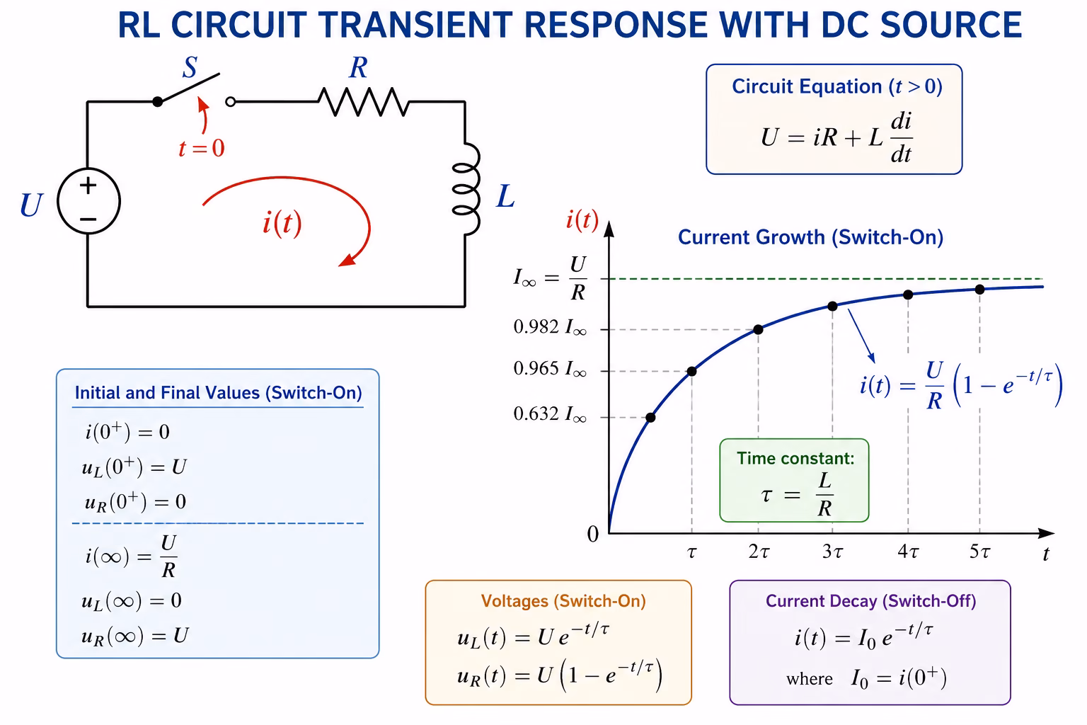
RL Circuit During Switch-On (Current Growth)
Applying Kirchhoff’s Voltage Law
After closing the switch, KVL gives:
U – uR – uL = 0
Since
uR = iR
and
uL = Ldi/dt
we obtain:
U = iR + Ldi/dt
Rearranging:
Ldi/dt + Ri = U
Solving the Differential Equation
Divide by L:
di/dt + (R/L)i = U/L
The equation can be solved by separating variables.
Rearrange:
di/dt = (U−Ri)/L
Thus:
di/(U−Ri) = dt/L
Integrating both sides:
∫di/(U−Ri) = ∫dt/L
Using substitution
x = U−Ri
gives
dx = −Rdi
or
di = −dx/R
Therefore
(−1/R)∫dx/x = t/L + C
which yields
(−1/R)ln∣x∣ = t/L + C
Returning to the original variable:
(−1/R)ln∣U−Ri∣ = t/L + C
Multiplying by −R:
ln∣U−Ri∣ = (−R/L)t + C1
Exponentiating:
U−Ri = Ce^(−Rt/L)
Hence
i = U/R – (C/R)e^(−Rt/L)
Determining the Integration Constant
At the switching instant:
i(0) = 0
Substituting:
0 = U/R – C/R
Therefore
C = U
and the current becomes
i(t) = (U/R)(1 − e^(−Rt/L))
This is the fundamental equation describing current growth in an RL circuit.
Time Constant of an RL Circuit
The quantity
τ = L/R
is called the time constant.
The current expression can be rewritten as:
i(t) = I∞(1 − e^(−t/τ))
where
I∞ = U/R
is the final steady-state current.
Significance of the Time Constant
At
t = τ
the current reaches:
i(τ) = I∞(1 − e^(−1))
Since
e^(−1) ≈ 0.3679
we obtain:
i(τ) ≈ 0.632 I∞
Thus, after one time constant, the current reaches approximately:
63.2%
of its final value.
For practical purposes, the transient process is considered complete after:
5τ
Voltage Across the Inductor
Using
uL = Ldi/dt
and
i(t) = (U/R)(1 − e^(−Rt/L))
differentiate:
di/dt = (U/L)e^(−Rt/L)
Therefore
uL(t) = Ue^(−Rt/L)
Initial and Final Values
At t=0:
uL(0) = U
At t→∞:
uL(∞) = 0
Initially, the inductor absorbs the entire source voltage.
Eventually, it behaves as a short circuit.
Voltage Across the Resistor
Since
uR = iR
substituting the current expression gives:
uR(t) = U(1 – e^(−Rt/L))
Initially:
uR(0) = 0
Finally:
uR(∞) = U
RL Circuit During Switch-Off (Current Decay)
Now suppose the source is disconnected while the resistor and inductor remain connected in a closed loop.
The stored magnetic energy drives current through the resistor.
Differential Equation
Applying KVL:
uR + uL = 0
Substituting:
Ri + Ldi/ dt = 0
or
di/dt = (−R/L)i
Separating variables:
di/i = (−R/L)dt
Integrating:
ln∣i∣ = (−R/L)t + C
Exponentiating:
i = Ce^(−Rt/L)
At t = 0:
i(0) = I0
Thus:
C = I0
and
i(t) = I0 e^(−Rt/L)
This equation describes the decay of current in an RL circuit.
Stored Magnetic Energy
The energy stored in an inductor is:
Wm = (1/2)Li^2
At steady state:
i = U/R
Thus:
Wm = (1/2)L(U/R)^2
This stored energy is released during the switch-off transient.
Physical Interpretation of the RL Transient Process
The transient response can be understood through energy transfer:
- The source supplies electrical energy.
- Part of the energy is dissipated as heat in the resistor.
- Part is stored in the magnetic field of the inductor.
- During switch-off, the magnetic field collapses.
- The stored energy is converted into heat in the resistor.
The exponential nature of the response originates from the proportional relationship between induced voltage and the rate of current change.
Practical Applications of RL Transients
RL transient phenomena are encountered in:
Electric Motors
Motor windings possess significant inductance, causing current rise delays during startup.
Electromagnetic Relays
Relay coils exhibit RL transient behavior whenever energized or de-energized.
Solenoids
The magnetic force builds gradually due to current growth.
Power Electronics
Switching converters must account for inductive transient effects.
Automotive Systems
Ignition coils rely on rapid magnetic field collapse to generate high voltages.
Conclusion
The transient response of an RL circuit is one of the most important examples of first-order dynamic systems in electrical engineering. Because inductors resist sudden changes in current, the current increases and decreases exponentially rather than instantaneously.
For the switch-on process:
i(t) = (U/R)(1 − e^(−Rt/L))
For the switch-off process:
i(t) = I0 e^(−Rt/L)
The characteristic parameter governing both processes is the time constant:
τ = L/R
These equations form the foundation for the analysis of inductive circuits, electromagnetic devices, power systems, and countless practical engineering applications.
Similar to the RC circuit, the differential equation:
Ldi/dt + Ri = U
can be solved in another way:
After dividing by L we get:
di/dt + (R/L)i = U/L
The solution to this differential equation is obtained as the sum of the solutions of the corresponding homogeneous equation and the particular solution.
In the first case, the equation needs to be solved:
di/dt + (R/L)i = 0
This means that:
di/dt = –(R/L)i
therefore, it is:
di/i = –(R/L)dt
After applying the integral:
ln (i) = –(R/L)t + ln (C)
ln (i) – ln (C) = –(R/L)t
ln (i/C) = –(R/L)t
i = Ce^(–(R/L)t)
To determine the particular solution, the assumed solution of the differential equation needs to be given. It is easy to conclude that it will be i = K (K is a constant). This means that di/dt = 0, so K = U/R or ip = U/R, so i = Ce^(–(R/L)t) + U/R.
Based on the initial conditions i = 0, t = 0, we get that C = -U/R, so:
i(t) = (U/R) (1 – e^(–(R/L)t)
A deeper physical interpretation of the RL time constant emerges from a simple dimensional argument.
The expression
e^(−Rt/L)
can be rewritten as
e^(−t/(L/R))
Since the exponent must be dimensionless, L/R must necessarily carry the dimension of time.
Indeed, from
U = L·(dI/dt)
we obtain
L = U·t/I
while Ohm’s law gives
R = U/I
Consequently:
L/R = (U·t/I)/(U/I) = t
This elegant result reveals that the RL time constant τ = L/R is not merely a parameter appearing in the mathematics of the solution – it is fundamentally a measure of time embedded in the physics of the circuit itself.