
Introduction
The transient response of electrical circuits is one of the fundamental topics in circuit theory and electrical engineering. While RC and RL circuits are governed by first-order differential equations, an RLC circuit contains both energy-storage elements—a capacitor and an inductor—which leads to a second-order differential equation and considerably richer dynamic behavior.
Depending on the relationship between resistance, inductance, and capacitance, the circuit may exhibit non-oscillatory decay, critical damping, or damped oscillations before reaching its final steady-state condition.
In this article, we derive the complete transient response of a series RLC circuit connected to a DC voltage source. Every mathematical step is presented in detail, and all possible damping conditions are analyzed.
Series RLC Circuit Connected to a DC Source
Consider a series circuit consisting of:
- Resistance R
- Inductance L
- Capacitance C
- DC voltage source V
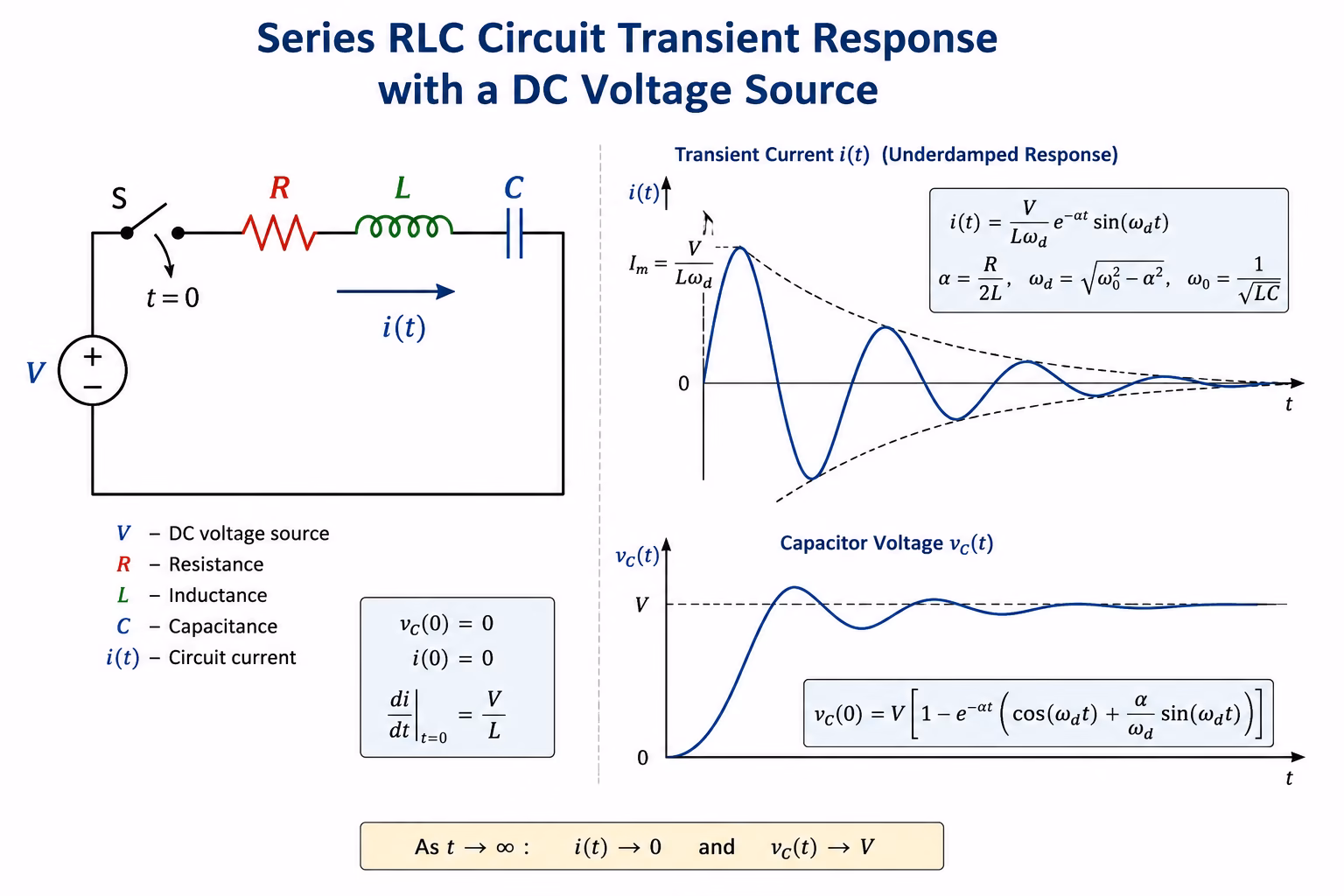
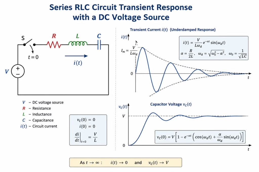
At time t = 0, the switch is closed and the source voltage is suddenly applied to the circuit.
The circuit current is denoted by:
i(t)
The capacitor voltage is:
vC(t)
The inductor voltage is:
vL(t)
The resistor voltage is:
vR(t)
Applying Kirchhoff’s Voltage Law
According to Kirchhoff’s Voltage Law:
V = vR + vL + vC
Using the constitutive equations of the circuit elements:
vR = R·i
vL = L·di/dt
vC = (1/C)·∫i dt
Substituting into Kirchhoff’s equation gives:
V = R·i + L·di/dt + (1/C)·∫i dt
This equation contains an integral term. To obtain a differential equation, differentiate both sides with respect to time:
dV/dt = R·di/dt + L·d²i/dt² + (1/C)·i
Since the source voltage V is constant:
dV/dt = 0
Therefore:
L·d²i/dt² + R·di/dt + (1/C)·i = 0
This is the governing differential equation of the transient process.
Standard Form of the Differential Equation
Divide the equation by L:
d²i/dt² + (R/L)·di/dt + (1/LC)·i = 0
To simplify the notation, define:
α = R/(2L)
where α is called the damping coefficient.
Also define:
ω₀ = 1/√(LC)
where ω₀ is the undamped natural angular frequency.
The differential equation becomes:
d²i/dt² + 2α·di/dt + ω₀²·i = 0
Derivation of the Characteristic Equation
Assume a solution of the form:
i(t) = e^(st)
Then:
di/dt = s·e^(st)
d²i/dt² = s²·e^(st)
Substituting into the differential equation gives:
s²·e^(st) + 2α·s·e^(st) + ω₀²·e^(st) = 0
Since e^(st) ≠ 0:
s² + 2αs + ω₀² = 0
This is the characteristic equation of the circuit.
The roots are:
s₁,₂ = -α ± √(α² − ω₀²)
The nature of these roots determines the type of transient response.
Overdamped Response
Condition for Overdamping
The circuit is overdamped when:
α > ω₀
or equivalently:
R > 2√(L/C)
The roots of the characteristic equation are real and distinct:
s₁ = -α + √(α² − ω₀²)
s₂ = -α − √(α² − ω₀²)
Current Response
The transient current is:
i(t) = A·e^(s₁t) + B·e^(s₂t)
where A and B are constants determined by the initial conditions.
Because both exponential terms decay with time, the current approaches zero without oscillation.
Critically Damped Response
Condition for Critical Damping
Critical damping occurs when:
α = ω₀
or:
R = 2√(L/C)
The characteristic equation has a repeated root:
s = -α
Current Response
The solution becomes:
i(t) = (A + Bt)e^(-αt)
This represents the fastest possible transient response without oscillation.
Critical damping is often desirable in measurement systems and automatic control systems.
Underdamped Response
Condition for Underdamping
Underdamping occurs when:
α < ω₀
or:
R < 2√(L/C)
The roots become complex conjugates:
s = -α ± jωd
where:
ωd = √(ω₀² − α²)
is called the damped natural frequency.
General Current Response
The transient current becomes:
i(t) = e^(-αt)[A cos(ωd t) + B sin(ωd t)]
An equivalent form is:
i(t) = Im·e^(-αt)·sin(ωd t + φ)
where:
Im = maximum current amplitude
φ = phase angle
The current oscillates while its amplitude gradually decreases due to the energy dissipated in the resistor.
Determination of the Constants
Assume an initially uncharged capacitor:
vC(0) = 0
and zero initial current:
i(0) = 0
At the switching instant:
V = L·di/dt
Therefore:
(di/dt)|t=0 = V/L
Starting from:
i(t) = e^(-αt)[A cos(ωd t) + B sin(ωd t)]
Applying:
i(0) = 0
gives:
A = 0
Thus:
i(t) = B·e^(-αt) sin(ωd t)
Differentiate:
di/dt = B·e^(-αt)[ωd cos(ωd t) − α sin(ωd t)]
At t = 0:
(di/dt)|t=0 = Bωd
Using:
(di/dt)|t=0 = V/L
gives:
B = V/(Lωd)
Therefore, the complete transient current is:
i(t) = (V/(Lωd))e^(-αt)sin(ωd t)
This is the classical expression for the underdamped transient current in a series RLC circuit.
Derivation of the Capacitor Voltage
Because:
i = C·dvC/dt
we obtain:
dvC/dt = i/C
Substituting the current expression:
dvC/dt = (V/(LCωd))e^(-αt)sin(ωd t)
Integrating yields:
vC(t) = V[1 − e^(-αt)(cos(ωd t) + (α/ωd)sin(ωd t))]
As time approaches infinity:
e^(-αt) → 0
and therefore:
vC(∞) = V
which confirms that the capacitor eventually charges to the source voltage.
Energy Exchange During the Transient Process
The capacitor stores electric-field energy:
WC = (1/2)CvC²
The inductor stores magnetic-field energy:
WL = (1/2)Li²
During the transient response, energy continuously oscillates between these two storage elements.
Meanwhile, the resistor dissipates energy as heat:
PR = i²R
Consequently, all transient oscillations eventually disappear.
Practical Applications of RLC Transient Analysis
Understanding the transient response of RLC circuits is essential in:
- Power electronics
- Electrical drives
- Communication systems
- Radio-frequency resonators
- Signal processing
- Analog filter design
- Control engineering
- Switching circuits
- Measurement systems
The same mathematical principles also appear in mechanical vibration theory and control-system dynamics.
Conclusion
The transient response of a series RLC circuit connected to a DC voltage source is governed by a second-order differential equation whose solution depends on the relationship between resistance, inductance, and capacitance.
Three distinct operating regimes exist:
- Overdamped response
- Critically damped response
- Underdamped response
Through a complete mathematical derivation, we obtained the governing differential equation, characteristic equation, transient current expressions, and capacitor voltage response. These results form one of the most important foundations of circuit theory and modern electrical engineering.